guglwizard.blogg.se

Diode cathode anode
Diode cathode anode


  1. #DIODE CATHODE ANODE HOW TO#
  2. #DIODE CATHODE ANODE INSTALL#

#DIODE CATHODE ANODE INSTALL#

I'm hoping to install some LED lights in one of my hotwheels cars. I'm watching some youtube videos as a complete noob to electronics (haven't touched circuits since highschool which is like 10+ years ago. Hi all, sorry if this is the wrong place. At this point I'm going to de-solder the powe Those connect to the potentiometer board but will need to be removed so the control board can be placed in a different orientation. Also note the two black socket connectors at the top of the board near the power supply. I'll re-use most of those to make connecting the controls easier, but I will have to remove the one that goes to the switch/led board. Most of the satellite boards are connected to the main board with those snap-in connectors. Note the two screws holding it in place at the bottom.Īlso need to remove this ground screw before you can lift out the main board. I ended up using only the main board and the board with the three main potentiometers.

diode cathode anode

Turns out there are 5 circuit boards inside: a main board and four satellite boards containing the controls and I/O. Okay so first things first, I had to open it up and see what I was working with. Here's the finished pedal for folks who aren't interested in the process: I made my goal to fit this into a Hammond 1590BBS, which at 1.5" tall is much closer to the other pedals on my board. I've seen a few re-housed DE7s online, but they are all in pretty large enclosures (like 2 inches tall). I didn't find a lot of information about this particular project online so I decided to (mostly) document my work and share it here in case any other DE7 fans want to do something similar. When the switch on mine started to fail recently I planned to replace it and thought it might be fun to re-house the pedal into a more attractive case. When I bought mine ten or so years ago they could be found for like 25 to 40 bucks, but now they tend to be a little more pricey. The Ibanez DE7 is one of my all-time favorite delays.

  • Then the reading should display a high resistance value ( OL condition ) hence the diode induces a very high resistance when it is reverse biased.This is a long post, but I wanted to share a bit about my most recent project in case anyone finds it helpful.
  • Then connect positive phobe to the cathode and negative phobe to the anode.
  • Then the reading should give a low resistance value hence it is forward biased.
  • Connect the positive phobe to the positive terminal of the diode (anode) and the negative phobe to the negative terminal of the diode ( cathode ).
  • #DIODE CATHODE ANODE HOW TO#

    How to Find Anode and Cathode in Diode using Analog Multimeter
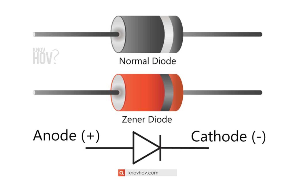
    diode cathode anode

    Diodes induce very high resistance when they are reverse biased.

  • If the display gets a very high resistance value or ” OL ” that means the diode is reverse biased where red phobe is on the cathode and the black phobe is on the anode.
  • If the display gets a low resistance value in a low resistance checking mode, then it’s forward biased and the red phobe is on the anode and the black phobe is on the cathode.
  • Check the readings on the display by rotating the central knob from low resistance modes to high resistance modes.
  • Keep the red phobe and the black phobe on either side of the diode.
  • diode cathode anode diode cathode anode

  • Set the central knob to the resistance testing mode where the Ohm symbol is indicated.
  • How to Find Anode Cathode of Diode using Ohmmeter ( resistance ) mode testing in the digital multimeter.
  • If the display didn’t show any value or it displays “OL”, that means there’s no current flowing through the diode and it’s in the reverse biased condition where the red phobe is on the cathode.
  • ( If the displayed voltage is about 0.6 – 0.7, then it’s a silicon diode which is forward biased and that value is 0.25 – 0.3 for Germanium diodes )
  • If there’s a voltage value is displayed, then the diode is forward biased and the terminal where u kept the red phobe is the anode and the terminal where u kept the black phobe is the cathode of the diode.
  • Keep the red phobe (+) and the black phobe (-) in either terminal of the diode.
  • Rotate the central knob to where the diode symbol is indicated which is the diode checking mode in the digital multimeter.


  • Diode cathode anode